Comparison of Radial Expansion of Stents
Stent Testing
by | RMBS 2008 | Publications, Compliance, High Speed Photography, Silicone Mock Arteries, Stent Testing
Comparison of Radial Expansion of Stents Within Mock Vessels Molded with a Target Bent Radius Versus Straight Mock Vessels Bent to a Target Radius
Ramesh R1, Conti JC2,3, Strope ER1, Thompson M1, Price KS1, Murray D1,
1 Dynatek Dalta Scientific Instruments, 105 E Fourth St, Galena, MO 65656
2 Department of Physics, Astronomy and Material Sciences, Missouri State University, Springfield, MO 65803
3 Harbin Engineering University, Harbin, China
RMBS 2008
Keywords
Radial expansion, stent durability, deflection, mock vessels, coronary artery
Abstract
Coronary artery disease results in hardening of the arteries. The main reason is that cholesterol and plaque build up on the inner walls of the arteries. This results in restricting the blood flow to the heart causing injury to the heart muscle. Recently, non-surgical processes are being used to open up restricted arteries thus improving blood flow. Stents, which can be commonly described as metal mesh, are placed inside the artery, thereby preventing the artery from collapsing following interventional treatment. Once the procedure is performed, the stent becomes an active dynamic member of the artery, expanding and contracting along with the vessel during changes in intravascular pressure [4].
In order to evaluate the long-term durability of products such as stents, the accelerated mechanical properties should be evaluated. In recent years, mock arteries have been used in evaluating the mechanical characteristics of vascular stents [5]. The effectiveness of in vitro experiments on stents significantly depends on the characteristics of the mock arteries. Two important characteristics are compliance and shape of the mock arteries. Compliance of the mock artery, also known as radial distension over a pressure differential, determines the load applied by the mock vessel on the stent being tested. This research work was conducted to evaluate the influence of the shape of mock arteries on the characteristics of stents during pulsatile loading. In vitro testing of coronary stents involves stents being deployed into cylindrical mock arteries and loaded to produce stent deflection (change in diameter) similar to in vivo conditions [6]. During the radial fatigue testing, distension or the load applied on the stent plays a very important role in evaluating the life of the stent. Uniformity of stent deflection may be important to ensure that the stent experiences worst-case conditions [7]. Recently, radial fatigue studies, which have traditionally been performed in straight mock vessels, have begun to be performed in mock vessels with static bends, in order to better replicate anatomical structures into which coronary stents are deployed [8]. This study was conducted to evaluate the uniformity of stent deflection in mock vessels manufactured with a curve versus vessels manufactured straight and then bent to the target radius [9-13].
Methods
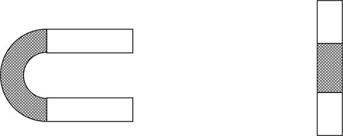
Two types of silicone mock arteries of internal diameter 2.9mm +/- 0.2mm were used. One of the mock vessels was manufactured with a 15 mm bend radius (pre-crv) and the other vessel had a straight cylindrical configuration (straight) and was mounted to obtain a 15mm bend radius (Figure 1) on a coating durability tester (Figure 2). The dynamic internal compliance of the pre-curved tubes was 4.89% +/- 0.25% per 100mm Hg, and that of the straight tubes was 4.52% +/- 0.25% per 100mm Hg; they were essentially the same.

Fig 1: Schematic representation of silicone mock arteries with stents deployed.
All the initial dimensional measurements of the mock vessels were made using LaserMike 183 (LaserMike, Dayton, OH). Commercially available coronary stents of mean diameter 3mm were deployed into these mock arteries. The straight cylindrical mock vessel was bent to replicate the vessel with bent configuration. The whole arrangement was tested using a Coating Durability Tester (CDT2) for radial fatigue (Coating Durability Tester Generation 2, Dynatek Dalta Scientific Instruments, Galena, MO). The CDT2 was used to create a distension of the mock artery with the stent deployed within the vessel. During this testing, a high-speed photographic camera (Fast Cam PCI 1280 Camera with Photron Motion Tools Software Version 1.05, Motion Engineering, Indianapolis, IN) was used to measure the distension of the stent directly. Previous studies have proven that distension of mock vessels is greatly influenced by testing frequency. This experiment was conducted at 72 bpm (1.2 Hz), using a cyclic pressure of 160/80mm Hg. The high speed photographic camera was used to measure the distension of the stent directly in both longitudinal and lateral planes. This was done to evaluate uniform expansion of the stent around the inner periphery of the mock vessel.
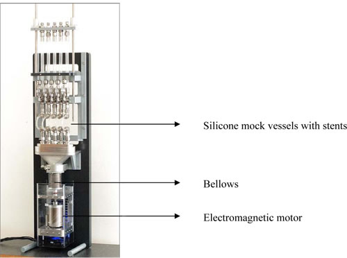
Radial Fatigue using CDT2: The Coating Durability tester is equipped with an electromagnetic motor which can compress the bellows at various frequencies up to 150 Hz. Compression of the bellows loads the stents [14].

Fig 2: Coating Durability Tester
Distension measurement using high speed photography [15-17]: A high speed photographic camera was used to determine the distension of the stent within the mock vessel. The camera’s associated software has the capability of analyzing the fast motion within the captured image. The basic principle for distension measurements using high speed photography is as follows: The high speed camera will track markings on the stent and the relative distance between the markings will change as the mock vessel expands and contracts. The percentage change in the chord length will be the same percentage change that occurs in the diameter.
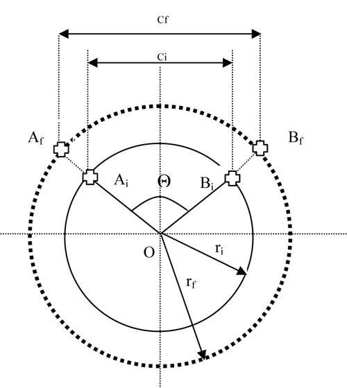
Let us assume the cross section of the mock artery to be a circle of radius r1 with center O.

Fig 3. Schematic representation of mock artery.
Select two points Ai and Bi on the circle such that the arc AiBi subtends an angle Θ at the center of the circle as shown in the Fig 3. Let ci be the initial length of the chord AiBi.
So:
ci = 2 sin (Θ/2) ri……….1
As the mock artery is being pulsed from lower pressure to higher pressure, let Af and Bf be the final positions of points Ai and Bi respectively and rf be the final radius. Let the distance between Af and Bf be cf. The % strain (%Є) in the chord length is given by change in the chord length divided by the original chord length.
% Є = ((cf-ci)100)/ci……….2
But,
cf = 2 sin (Θ/2) rf……….3
Therefore,
% Є =(rf – ri)/ ri……….4
Six measurements were made on each of the straight tubes that were then bent, and the tubes manufactured in the bent morphology. Two sets of apices were chosen as measuring points on each stent, one set on the lateral side and one set on the dorsal side.
Results
Table 1 is a summary of the measured percent stent deflections.
| Camera data | Vessel style | Camera view | Cyclic pressure | Percent deflection | Mean deflection |
| pcv-dva-1.2Hz-BB | pre-crv | dorsal-apex | 160/60 | 1.25 | |
| pcv-dva-1.2Hz-CC | pre-crv | dorsal-apex | 160/59 | 1.30 | 1.28 |
| pcv-dva-1.2Hz-DD | pre-crv | dorsal-apex | 160/60 | 1.30 | |
| pcv-lva-1.2Hz-AA | pre-crv | lateral-apex | 160/60 | 1.05 | |
| pcv-lva-1.2Hz-BB | pre-crv | lateral-apex | 160/60 | 1.36 | 1.27 |
| pcv-lva-1.2Hz-CC | pre-crv | lateral-apex | 160/60 | 1.40 | |
| sv-dva-1.2Hz-AA | straight | dorsal-apex | 160/61 | 0.89 | |
| sv-dva-1.2Hz-BB | straight | dorsal-apex | 162/61 | 0.90 | 0.82 |
| sv-dva-1.2Hz-CC | straight | dorsal-apex | 160/61 | 0.68 | |
| sv-lva-1.2Hz-AA | straight | lateral-apex | 162/61 | 0.85 | |
| sv-lva-1.2Hz-BB | straight | lateral-apex | 162/61 | 0.65 | 0.78 |
| sv-lva-1.2Hz-CC | straight | lateral-apex | 161/61 | 0.86 |
Table 1: Deflection Results
In these experiments there is a measurable difference in the percent deflection found with the straight tubes that were bent during mounting versus tubes molded in a curved morphology. Comparing the dorsal and lateral measurements, percent expansion appeared to be the same in orthogonal planes.
Discussion
Many manufacturers report at standards meetings and the Cleveland Clinic Stent Summit that the currently used in vitro testing protocols do not predict stent failure in vivo. One of the variables that could be affecting these results might be the mechanical properties of the mock arteries used and how the manufacturing techniques used to produce these mock arteries influence these properties.
References
1 ) Conti, JC, Strope, ER, Price, KS, and Goldenberg, LM, The High Frequency Testing of Vascular Grafts and Vascular Stents: Influence of Sample Dimensions on Maximum Allowable Frequency, Biomedical Sciences Instrumentation, 35, 339-346, (1999)
2 ) Conti, JC, Strope, ER, Rhode, DJ, and Spence, LD, Frequency Dependent Radial Compliance of Latex Tubing, Biomedical Sciences Instrumentation, 33, 524-529 (1997)
3 ) Conti, JC and Strope, ER, Radial Compliance of Natural and Mock Arteries: How This Property Defines the Cyclic Loading of Deployed Vascular Stents, Biomedical Sciences Instrumentation, 38, 163-171, (2002)
4 ) Conti, JC, Strope, ER, and Spence, LD, State of The Art Stent Testing: A Review of Protocols, Concerns And Considerations For The End User, The Society For Cardiac Angiography and Interventions, 1997
5 ) Conti, JC, Strope, ER, and Gregory, R., High Frequency Testing Of Nitinol Stent Material, Society of Biomaterials, 1999
6 ) Conti, JC, Strope, ER, and Price, KS, Sources of Error in Monitoring High Speed Testing of Vascular Grafts, Biomedical Sciences Instrumentation, 34, 240-245, (1998)
7 ) Schmidt, W, Behrens, P, and Schmitz, KP, New Aspects Of In Vitro Testing Of Arterial Stents Based On The New European Standard EN 14299, Mastering Endovascular Techniques: A Guide to Excellence, Lippincott Williams and Wilkins, 2006
8 ) Liao, R, Chen, JSY, Messenger, JC, Groves, BM, Burchenal, JEB, and Carroll, D, Four Dimensional Analysis of Cyclic Changes In Coronary Artery Shape, Catheterization and Cardiovascular Interventions, 55, 344-354, (2002)
9 ) Conti, JC, Strope, ER, Rohde, DR and Greisler, HP, A New Technique to Determine Vascular Compliance In Vivo, National Heart Lung and Blood Institute Contractors Meeting. Louisville, KY, 1989
10 ) Gonza, ER, Mason, WF, Marble, AE, and others, Necessity for Elastic Properties in Synthetic Arterial Grafts, Can. J. Surg., 17,176-179 (1974)
11 ) Ramesh, R, Strope, ER, Price, KS, and Conti, JC, Frequency Dependent Hysteresis of Silicone and Latex Mock Arteries Used in Stent Testing, Biomedical Sciences Instrumentation, 41, 163-168, (2005)
12 ) Ramesh, R, Conti, JC, and Strope, ER, Single Versus Double Ended High Frequency Pressurization of Mock Arteries: Symmetry of Expansion, Biomedical Sciences Instrumentation, 42, 446-51, (2006)
13 ) AAMI/ISO Standard ISO/CD- V-1 25539-01:2003 and ANSI/AAMI VP-20, 1994
14 ) Conti, JC, Strope, ER, Ramesh, R, Conti, C, and Watkins, A, A Comprehensive Protocol and Procedural Considerations Designed to Evaluate the Shedding of Particles from Drug Eluting Stents, Materials and Processes for Medical Devices, 2007
15 ) Kattekola, B, Conti, JC, and Strope, ER, High Speed Photographic Verification of Intravascular Stent Strains During Accelerated Durability Testing, Biomedical Sciences Instrumentation, 40 (2004)
16 ) Ramesh, R, Conti, JC, and Strope, ER, Mock Artery Distension: Comparison Of Optical, Mechanical and Theoretical Results, Biomedical Sciences Instrumentation, 43, 46-53, (2007)
17 ) Ramesh, R, Conti, JC, and Strope, ER, Linear Elastic Mechanics of Mock Arteries: Empirical Versus Theoretically Predicted Pulsatile Stent Deflection, Biomedical Sciences Instrumentation, 43, 54-62, (2007) Biomedical Sciences Instrumentation, 44, 189-194, (2008) Dynatek Labs


