Introduction
According to international standards, the deflection of a stent or stent-graft being tested must be measured, by directly observing the stent.
Evaluation of High Speed Photography to Measure Stent Deflection
Durability or fatigue testing of stents and stent-grafts involves the deployment of the vascular device into a compliant silicone mock vessel which undergoes pulsatile deflection on the test platform.
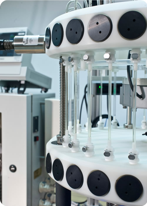
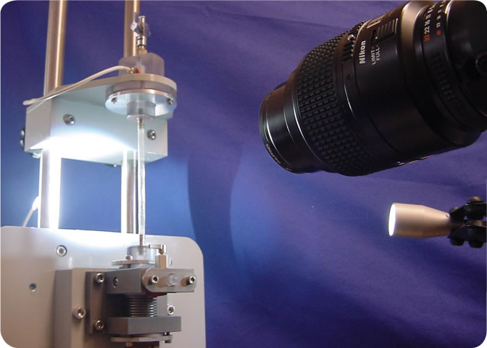
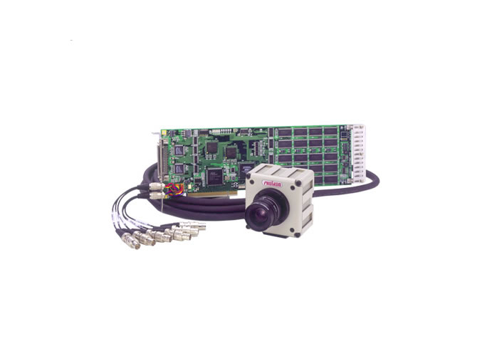
To evaluate high speed photographic verification of stent deflection, researchers at Dynatek used the DCT Dynamic Compliance Tester (Fig.1) and a FastCam PCI 1280 High Speed Camera (Fig.3). An intravascular stent graft (8cm long) was deployed in a compliant silicone mock vessel (28.12 mm OD; 22.55 mm ID). The dimensions of the silicone mock vessel were measured using a laser micrometer.
The inside wall of the mock vessel was marked with three sets of points and the outside wall was marked with four sets of points, to create landmarks’ on the vessel that can be tracked by the camera during pulsation.
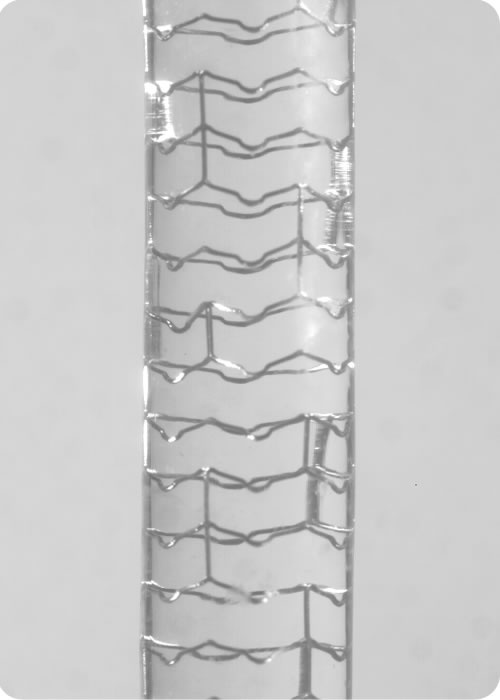
Two apical points on the stent were chosen and marked for monitoring. The mock vessel with the stent graft deployed inside it was mounted on the DCT. The mock vessel/stent combination underwent a pulsatile pressure regime that varied from 0 to 120 or 80 to 120 mmHg at 72 bpm, after mounting on the DCT.
High Speed Video Camera
A high speed photographic camera was used to determine the distension of the stent within the mock vessel. The camera’s associated software has the capability of analyzing the fast motion within the captured image.
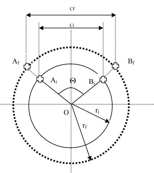
The basic principle for distension measurements using high speed photography is as follows: The high speed camera will track pairs of landmarks on the stent and the distance between the marks will change as the mock vessel expands and contracts. The percentage change in the chord length will be the same percentage change that occurs in the diameter. A video recording of the mock vessel/stent graft combination was made while it was undergoing deflection. The deflection measurements were taken at 500 fps, 1280 x 1036 resolution, at a 1/500 sec shutter speed.
Measurements were made in both manual and automatic modes. In the manual mode, the distance between two landmarks is manually obtained by counting the pixels between the markings. In automatic mode, the calibrated software associated with the camera automatically calculates the distance between the markings.
Measurement Theory
In the Chord Theory of measurement, the strain in the mock vessel is calculated using 2 points, A and B in a circle with radius r and center R (Fig. 4). The outline of the vessel cross-section at rest is shown by the dark circle in the figure, and the dotted circle represents the vessel after undergoing strain. When pulsed, the radius increases and the chord represented by AB expands to the chord represented by CD, showing that the strain in chord length is equivalent to radial strain. For a detailed treatment of the theory behind strain measurement.
Conclusion
High speed photography enables validation of stent deflection during durability testing of stents. Manual tracking gave similar results when compared to automatic tracking, and inside compliance of the mock vessel was found to be higher than the outside compliance.
Laser Micrometry vs. High Speed Photography
Importantly, any method e.g., laser micrometry, used to measure the change of the OD of the mock vessel does not measure the change in the dimensions of the stent inside it. Therefore, direct observation or direct measurement (as prescribed by regulations) is required for reliably determining stent deflection during stent durability testing. High speed photography constitutes a method of direct observation and direct measurement of the stent.
Laser micrometer measurements are appropriate, however, to monitor the operating conditions of the test, once such conditions are established by high-speed photography.
Dynatek’s SVP-24 and UST radial fatigue testers and CDT coating durability testers feature laser micrometers (Fig. 5) to measure mock vessel deflection. We also offer optional high speed video cameras where precise tracking of two or more points on the stent is required to measure cyclic expansion of the stent.
References:
1. ASTM F2477-07. Standard Test Methods for in vitro Pulsatile Durability Testing of Vascular Stents.
