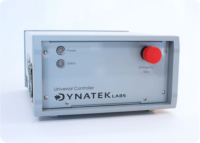
Universal Controller for HyperDrive
Dynatek’s new Universal Controller is a powerful controller that has been redesigned to control and monitor Dynatek’s SVP/UST radial fatigue stent testers, the CDT family of coating durability testers, and the Acute Particulate tester.
Data Integrity and Security
The UC creates a comprehensive data file that can log all test parameters and alarm events in TDMS format at user-configurable intervals of one or five minutes for the entire duration of the test. 21 CFR Part 11 lists a number of requirements for Electronic Records1 and the UC offers the following benefits for users:
• An electronic record of the complete test in human readable form for inspection, review and copying by regulatory agencies.
• Validation of the system to ensure accuracy, reliability, and consistent intended performance.
• System access limited to authorized individuals.
• Protection and encryption of records to enable their accurate and ready retrieval.
• An audit trail in the form of a secure, computer-generated time-stamped electronic record that allows the reconstruction of the events in the test.
• Provides verification of test parameters.
• Allows annotation and explanation by the operator of any anomalous event.
The UC outputs the data log file to the PC at pre-defined periods, in TDMS format. An exact copy of the data is automatically zipped in an archive with 256-bit encryption.
Sophisticated Alarm Processing
The UC allows you to add alarms to parameters of your choice, to either allow the user to examine specific performance criteria in the test or shut down the test altogether. These alarms are user-configurable and are triggered when the value of the parameter being measured exceeds a preset high or low value.
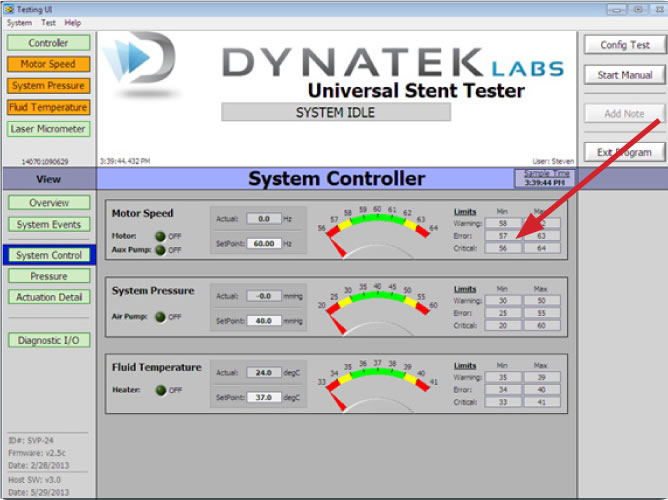
All user-configurable alarms can be configured with any appropriate alarm level and action. Alarms can be used with Warning or Error limits to warn of the movement of any parameter towards unfavorable process conditions, or as a Critical Limit to stop the test in the case of a parameter exceeding an unacceptable operating limit (Fig. 1).
Alarms on the UC can be used in a wide variety of process applications to provide:
• An independent emergency shutdown to avert undesirable system conditions.
• Ample warning and response time to the operator to intervene and avoid a system shutdown.
• Alarm trips that are user-defined.
• A user-defined ‘dwell time,’ where an alarm is triggered only after an alarm state has lasted longer than the dwell time, e.g., preventing spikes caused by an unstable power grid from shutting down the unit.
The user can annotate any event or alarm condition that has been logged, and all data and annotations are date- and timestamped in the log file in chronological order.
CDT and UST/SVP System Control
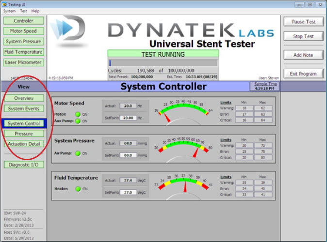
The UC’s advanced controller software allows the user to monitor and control critical controller functions in the CDT and UST/SVP testers via the System Controller tab (Fig. 2). The System Controller view lets you choose System Events, System Control, Pressure and Particle Count options in a well-laid out screen, allowing ease of navigation and use.
Hyperdrive Motor Controls
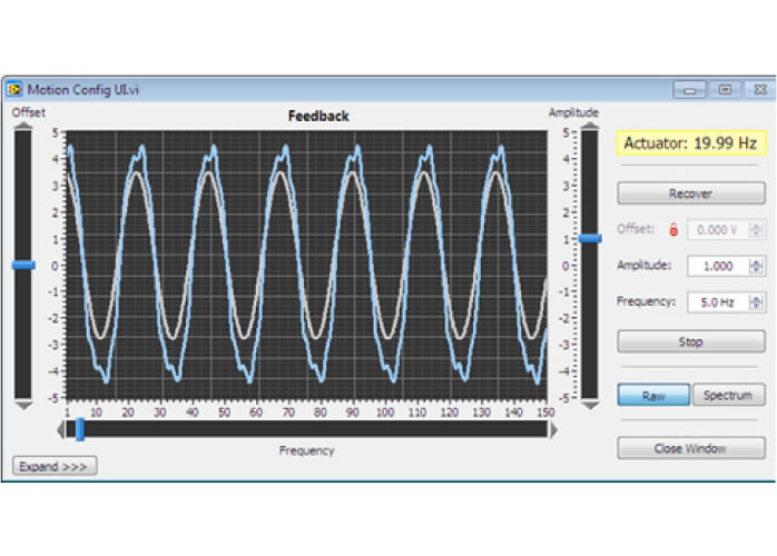
The UST/SVP and CDT family of stent testers all utilize the Hyperdrive Motor system to generate pulsatile motion in the test frame. The UC drives, monitors and controls the Hyperdrive motor via the Motion Configuration Screen (Fig. 3) which is accessed from the System Actuation screen.
The Motion Configuration screen displays the:
a. Frequency or cycles per second at which the HyperDrive motor is running. The frequency can be typed in by the user as a number in the designated field.
b. Amplitude or the stroke length of the motor can also be changed simply by typing in the number in the field.
c. Expand/Collapse function which shows or hides the Laser Micrometer portion of the Motion Configuration user interface.
d. Raw/Spectrum display, which can toggle between waveform and frequency analysis display.
Graphical Display
The pressure tab opens the Tube Pressure screen. This screen shows the graphical representation of mean and amplitude of the pressure in individual tubes. The user can select from groups or ‘banks’ of five tubes in the CDT and UST/SVP testers, and also which tube in the bank to display the graph for. All graphs have a selectable buffer of 1, 5, or 10 seconds. This screen has a pressure waveform capture that allows the user to create a file to log the pressure waveforms.
UC Software –Laser Micrometer, Closed Loop Feedback and SPC Analysis
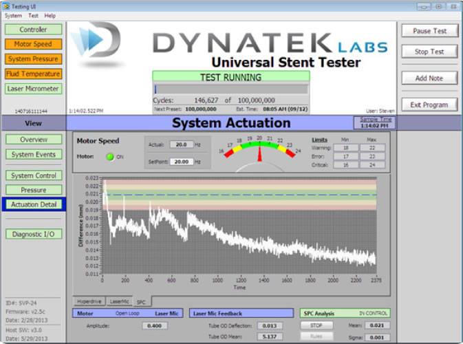
The software uses a laser micrometer to measure the outer diameter of a sample tube. This feedback is displayed in two ways on the Actuation Detail screen (Fig. 4). First, an analog waveform shows real time feedback of all analog data taken from the laser micrometer. Second, there is a display box underneath the graph that shows “Tube OD Deflection,” which is calculated by the laser micrometer and represents the difference of the maximum tube OD and the minimum tube OD for a given cycle, in millimeters.
The UC software is able to maintain a given tube OD deflection using closed loop feedback on this parameter. Controls for this are on the Motion Config user interface. The “OD Defl. SP” is the setpoint for tube OD deflection and can either be locked to the current feedback, or manually entered. However, there is a maximum value that the motor output is allowed to deviate from its initial output, so it is not possible to simply enter any number in this box and have the tester tune its output to match that tube OD deflection.
SPC Analysis is used to characterize the performance of the closed loop operation. When “Start” is selected once in closed loop operation, data collection begins, and a graph will appear to give details. A window displaying “Rules” will allow the user to configure the parameters for the SPC analysis.
Modern standards require the visualization of the device to determine the amount of deflection. This renders the laser measurement only useful to assess repeatability of pulsatile fluid volume but not the stent or device deflection.
Test Recall
The UC software has a Test Recall feature in the event that a test is prematurely aborted – either by user command or power loss/emergency stop. This featured is accessed easily by choosing the “Test” pull-down menu at the top of the screen and selecting “Recall Test” to display the test parameters of the most recent test.
The Test Recall feature does not allow the user to edit any test parameters except cycle count presets, as the software is recalling the exact configuration of the test the user intends to recall. The UC software is so easy to use that you can resume the test from the point at which it stopped simply by selecting “Start Test.”
References
1. 21 CFR Part 11, Subpart B, 11.10. Controls for closed systems
2. ISO/AAMI 5840:2013. Cardiovascular Implants – Parts 1,2 and 3: Heart valve substitutes
Key UC Hardware Features
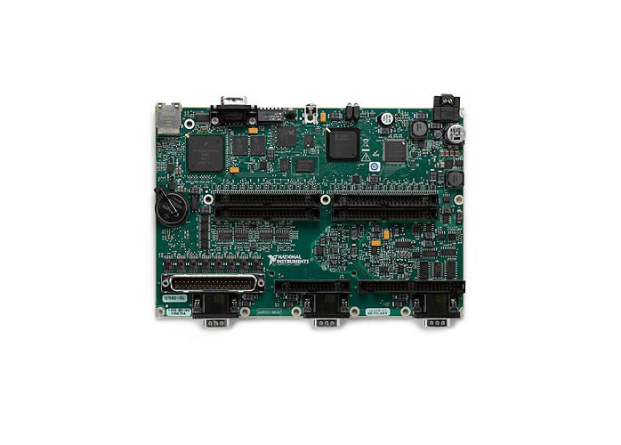
At the heart of the UC is the powerful, high-speed National Instruments 400 MHz sbRIO-9632 board, with a Real-Time Operating System (RTOS) and a 2Mgate Field Programmable Gate Array (Fig. 5). The RTOS allows the UC to handle data coming in at high speed, without buffering delays. The FPGA is a dedicated piece of hardware that does not depend on the operating system to function. Thus, different functions can run independently and not have to compete for the same processing resources, creating a reliable, robust, high-performance controller that can handle high speeds and high volumes of real time data. For hardware specifications, see last page.
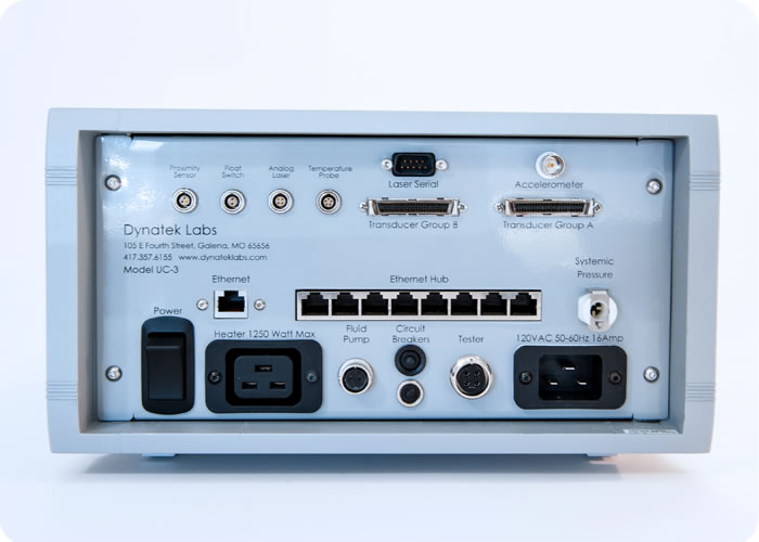
Universal Controller Hardware Specifications
|
Description
|
Specifications
|
|---|---|
|
Proximity Sensor
3-pin input
|
Proximity sensor to monitor rpm of motor with feedback loop to controller
|
|
Float Switch
2-pin input
|
Float switch to monitor fluid volume in capacitance tank
|
|
Analog Laser
4-pin I/O
|
Analog laser input/output for laser controller |
|
Temperature Probe 5-pin input |
Temperature probe used to monitor temperature of test fluid |
|
Laser Serial I/O
|
9-pin RS232 Serial Bus for sending and receiving information to/from laser micrometer. |
| Accelerometer BNC port | Connects to Accelerometer |
| Transducer Group A & B 50-pin I/O | Two 50-pin connectors for mating with up to 20 transducers |
| Ethernet port | Standard Ethernet port connects UC to computer |
| Ethernet hub | Standard eight-port Ethernet hub for connecting up to 20 particle counters |
| Female connector | Receives 1/8” hose barb coupling insert for systemic pressure tube |
| Power switch | Turns power on or off to the UC |
| Heater output | Drives heater to maintain test fluid temperature |
| Fluid Pump J1 connector | Fluid pump |
| Tester J8 connector | Drives motor |
| 16 Amp socket | Main 120 VAC 50-60 Hz power input |
| Power light | Power light is green when unit is on and dark when the unit is off |
| Status light | Status light is green when a test is underway, red when controller is booted and ready to be activated or yellow when operator attention is needed |
| Emergency stop | Emergency stop push button disconnects power supply and heater from power source |
| CPU | Included standalone PC with flat-screen monitor interfacing with UC |

