Straight Mock Vessels Bent to Radius vs. Curved Mock Vessels: Effect on Stent Deflection
Introduction
Mock vessels are routinely used to test the long-term durability of stents and stent grafts. The compliance and shape of mock vessels are directly responsible for the effectiveness of radial fatigue testing of stents deployed inside them. Mock vessels apply a recoil load to stents being tested and the combination of pulsatile pressure and mock vessel compliance determines this load. The compliance of the mock vessel is defined as radial distension over a pressure differential. To more closely mimic the properties of the coronary artery, stents that have been tested in straight vessels are increasingly being tested in curved mock vessels. This paper describes experiments to compare the properties of straight vessels bent to a 15 mm radius of curvature to ones built with this curvature.
Objective & Materials
To evaluate the effect of mock vessel characteristics on stent deflection, research was carried out at Dynatek Labs, where two kinds of mock silicone vessels were used: one fabricated with a 15 mm bend radius (pre-crv, Table 1) and the other vessel with a straight cylindrical configuration (straight, Table 1) that was manually bent into a curve to obtain a 15 mm bend radius.
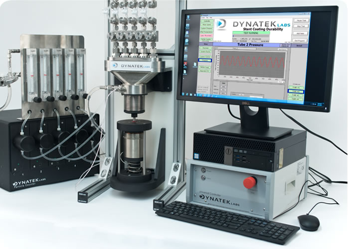
The mock vessels with commercially available stents deployed inside them were mounted on the CDT-5 Coating Durability Tester. Mock vessel measurements were made with a laser micrometer. The dynamic internal compliance of both types of mock vessels were similar: compliance of precurved tubes was 4.89% +/- 0.25%, and that of the straight tubes was 4.52% +/- 0.25% per 100 mm Hg.
Test Platform
Dynatek’s CDT-5 is furnished with a bellows that generates pulsatile pressure, creating a distension of the mock vessel in which the stents are deployed. Testing was performed at 72 bpm (1.2 Hz), with a cyclic pressure of 160/80 mmHg.
The stent distension created by the CDT-5 was tracked by a commercial high-speed video camera with specialized software. The camera was capable of measuring stent distension in both longitudinal and lateral planes, to evaluate uniform distension of the stent around the luminal surface of the mock vessel.
Two marks made on each stent are followed by the high-speed camera, which tracks the relative distance between these marks as the stent undergoes repeated distension. For a detailed description of the test methodology, please see the reference below.

Results
Table 1 below shows a summary of the stent deflections obtained by high-speed photography:
|
Camera
data |
Vessel
style |
Camera
view |
Cyclic
pressure |
Percent
deflection |
Mean
deflection |
|---|---|---|---|---|---|
| pcv-dva- 1.2Hz-BB |
pre-crv |
dorsal-apex |
160/60 |
1.25 |
|
| pcv-dva- 1.2Hz-CC |
pre-crv |
dorsal-apex |
160/59 |
1.30 |
1.28 |
| pcv-dva- 1.2Hz-DD |
pre-crv |
dorsal-apex |
160/60 |
1.30 |
|
| pcv-lva- 1.2Hz-AA |
pre-crv |
lateral-apex |
160/60 |
1.05 |
|
| pcv-lva- 1.2Hz-BB |
pre-crv |
lateral-apex |
160/60 |
1.36 |
1.27 |
| pcv-lva- 1.2Hz-CC |
pre-crv |
lateral-apex |
160/60 |
1.40 |
|
| sv-dva- 1.2Hz-AA |
straight |
dorsal-apex |
160/61 |
0.89 |
|
| sv-dva- 1.2Hz-BB |
straight |
dorsal-apex |
162/61 |
0.90 |
0.82 |
| sv-dva- 1.2Hz-CC |
straight |
dorsal-apex |
160/61 |
0.68 |
|
| sv-lva- 1.2Hz-AA |
straight |
lateral-apex |
162/61 |
0.85 |
|
| sv-lva- 1.2Hz-BB |
straight |
lateral-apex |
162/61 |
0.65 |
0.78 |
| sv-lva- 1.2Hz-CC |
straight |
lateral-apex |
161/61 |
0.86 |
Discussion
A review of Table 1 shows a significant difference in the percent deflection between stents deployed in straight vessels that were bent into a given radius versus molded curved vessels.
When a straight tube is bent, the outer wall of the bend undergoes tension, and the inner wall of the bend undergoes compression. Tension of the outer wall leads to thinning of the material at that location, affecting compliance of the mock vessel.
In Fig. 3, a curved tube undergoes equal forces on the inner and outer surfaces of the bend (A), resulting in uniform thickness of the mock vessel at the section indicated by the red line. A straight tube bent into a desired radius (B) results in tension on the outer wall, and thickening of the inner surface of the bend, shown in the crosssection at the red line. The cross-section in B also shows the outer wall moving towards the center of the lumen of the mock vessel; the wall before tension has set in is indicated by the dashed line.
The deformation that the straight mock vessel undergoes when it is bent into a desired radius affects the deflection of the stent deployed in it.
Conclusion
Dynatek fabricates straight, curved and custom mock vessels with a wide range of internal diameters and compliances. When specifying a mock vessel from your mock vessel vendor to deploy a curved stent, it is critical that you specify that the mock vessel be fabricated as a curved tube, not a straight tube bent into the required shape.
Mock vessels that are molded in the curved configuration offer significantly more accurate stent deflection data than straight vessels that are bent into shape.
Reference
Comparison of Radial Expansion of Stents within Mock Vessels Molded with a Target Bent Radius Versus Straight Mock Vessels Bent to a Target Radius.
R. Ramesh et al.
Biomedical Sciences Instrumentation, 44, 189-194, (2008).


