The Design and Laser Evaluation of a Pulsatile Flow Standard
Doppler Ultrasound
by | SBEC 1998 | Publications, Doppler Ultrasound
The Design and Laser Evaluation of a Pulsatile Flow Standard
Seventeenth Southern Biomedical Engineering Conference, Proceedings, 150, (1997)
Conti, J.C.,1 Strope, E.R., Rohde, D.J.
Dynatek Dalta Scientific Instruments, Fourth and Main, Galena, MO., 65656
1 Department of Physics, Southwest Missouri State University
SBEC 1998
In our laboratory we repeatedly have a need to be able to calibrate a variety of flow and velocity instruments that are used in various hydro-dynamic testing. There are many other laboratory applications including a clinical ultrasound laboratories and laser doppler velocimetry facilities that could utilize a device that would increase their reliability in their flow measurements.
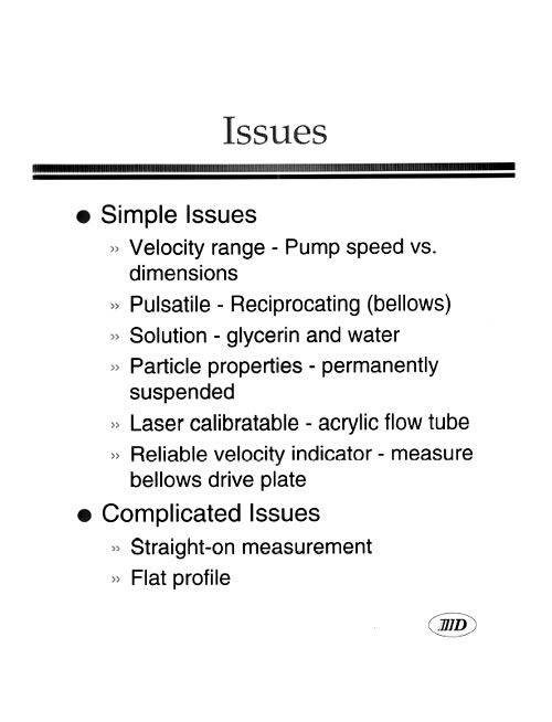
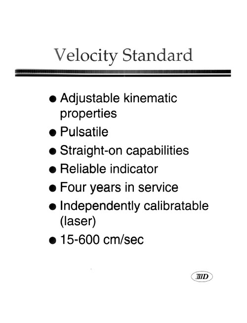
We embarked on a design program to produce a pulsatile flow system that was portable, easy to use, precise, accurate, reliable, and stable over time. In addition, their device had to be optically clear to be utilized with laser systems and in addition needed to have ports that allowed straight-on measurements using ultrasound as the energy source.
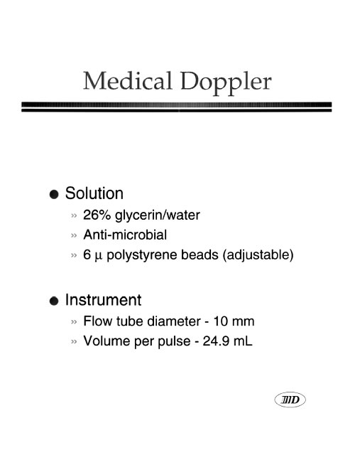
The keys to developing a system like this included a knowledge on the kinematic viscosity of the fluid that would be used, control over the geometry and compliance of the system. In addition, matching the rheological and mechanical properties of the system to the use of materials that would allow us to access the flow optically and ultrasonically. Our specific use was to calibrate clinical medical ultrasound instruments as well as magnetic flow probes in our facility.
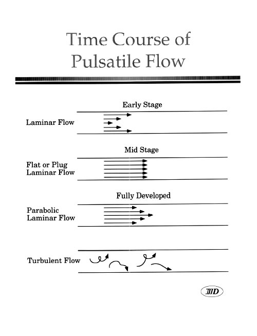
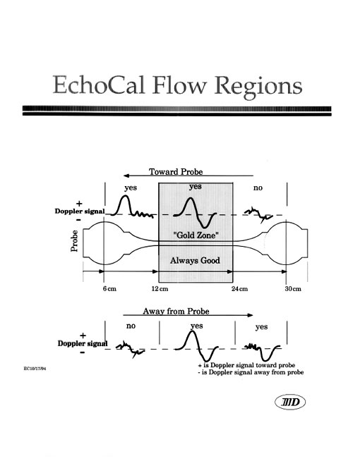
Figure 1 shows a partially exposed side view of the mechanical approach that we took to develop this calibration system. A blank horsepower 20-to-1 gear reduction motor was used with a timing belt to drive an accentric cam which moves a central plate left and right in the system. On each side of the central plate was mounted a single bronze bellow. On the discal portion of the bronze bellow a flow tube indicated here with the dots exited and turned 90° and entered a holding reservoir. The volume of the holding reservoirs had to be adjusted so as to eliminate any final turning of liquid into the flow tube, which would cause turbulence. During pumping the liquid would enter the reservoir and then would be constricted down using a nozzle so as to allow for rapid flow development. This flow developed fully by the end of the constricting region. At each end of the flow tube, just at the outside of the entrance reservoirs windows could be mounted either with glass or acrylic if optical clarity was needed or with PVC if ultrasonic probes were used. In addition, the full chamber was made out of acrylic so that laser calibration and/or analysis could be done.

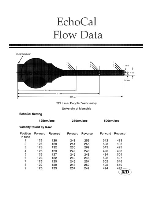
Figure 2 shows a summary of the velocities found using laser doppler anemometry at various points along the flow tube. As you can see, the forward and reverse flows are both within a few percent of the number predicted on the front of the flow calibrator.
This flow calibration device is accurate to within a few percent of the indicated value on the front panel. It is very easy to use and requires only turn on followed by adjustment of one knob to produce the peak velocities of interest. The system is portable and is easily transported from bench to bench or laboratory to laboratory.
This flow device offers us a simple easy to use convenient accurate and reliable way to calibrate ultramagnetic, ultrasonic or optical devices and greatly simplifies the process of flow probe or flow system calibration.

Slides from presentation


![]()
Dynatek Labs, Inc.
105 East 4th Street
Galena, MO 65656
417.357.6155
800.325.8252
fax 417.357.6327