Evaluating the in situ Loading and Accelerated Durability of Barbs …
Stent Testing
by | RMBS 2000 | Publications, Barb Stent, Stent Testing
Evaluating the in situ Loading and Accelerated Durability of Barbs Located on Bifurcated Aorto-Iliac Stent-Grafts
Biomedical Science Instrumentation, 36, pp. 93-98, (2000)
James C. Conti1, Elaine R. Strope
Dynatek Dalta Scientific Instruments, Fourth and Main St., Galena, MO 65656
1 Southwest Missouri State University, Dept. of Physics
RMBS 2000
Abstract
A special three-part protocol has been generated for the isolated durability testing of stent barbs. This triple protocol includes an initial evaluation on a cardiovascular duplicator to determine the loading per barb that occurs during normal flow through the stent-graft. The next stage of this protocol determined the frequency response characteristics of the bending point where the barb attaches to the stent to allow for the determination of the appropriate frequency to carry out the accelerated testing. The final part of the test includes high speed bend testing at frequencies determined in the second part of the methods to determine the long term durability of the isolated barb stent unit. The results of this testing indicated that under normal cardiovascular conditions each barb is experiencing a loading of 20 grams peak during maximum forward flow. Loading the isolated barb/stent segment at 600 beats per minute (bpm) for 400 million cycles indicated no tendency for these barbs to experience a change in physical properties. During this testing there were no barbs that broke.
Keywords
aorto-iliac, stent-graft, durability, fatigue, stent, accelerated
Introduction
Recently, aorto-iliac aneurysms have been treated with stent-grafts delivered to the site via catheter. However, sometimes the stent-graft can gradually move more distally due to hydrodynamic drag on the bifurcation point as well along the rough surface of the fabric of the graft before cellular ingrowth has occurred. One solution is to introduce barbs along the most proximal portion of the stent-graft to anchor it in place. There have been clinical examples, however, of these barbs breaking due to the repeated loading experienced where they are attached to the stent-graft. It was the focus of this study to specifically evaluate the expected in vivo pulsatile loading that a deployed stent-graft would experience and then complete accelerated durability testing at this target loading at a frequency that the isolated stent-graft segment could not respond to.
Materials and Methods
It was our intention to design an experimental set-up and method that would evaluate the worst case scenario that this bifurcated device would experience when deployed into the descending aortic-iliac bifurcation. We made cardiac output decisions based upon the information found in the text book Circulation , [1]. In this case, the authors found that under intense exercise (the worst case flow situation) cardiac output of a healthy individual approaches 25 Lpm. In addition, under these circumstances 65% of the flow has been directed away from the aorta by the time that the descending thoracic aorta just proximal to the bifurcation is reached. As a result, we tuned all of our experiments to deliver cardiac output of 8.75 Lpm through the aortic segment, at a pulse rate of 90 bpm, in phosphate buffered saline at 37° C. We felt that this testing would represent a worst case scenario. The initial experiments were designed to evaluate the amount of load that each barb would experience during these worst case pulsatile experiments.
The aorto-iliac bifurcated device would be deployed into a synthetic aorta that had been specifically designed and calibrated according to two critical pieces of information. The first was that the radial compliance of the device had to approximately replicate that of a healthy human aorta. We chose a radial compliance of 4% based upon results that Dr. Howard Greisler and the author have obtained during experimentation presented at the National Heart, Lung and Blood Institute, [2]. In addition to the pre-defined radial compliance of the tube, it was necessary to determine the longitudinal compliance of the tube since this would be the final measurement used to determine how the barbs were pulling of the aortic segment during experimentation.
The bifurcated aorta was mounted on a mechanical dynamic compliance tester and the radial compliance evaluated at pressures up to 120mm Hg at 90 bpm. The synthetic aorta was then stretched with calibrated loading to generate load vs. length data. The synthetic bifurcated aorta system was then mounted onto a custom pulse duplicator set up such that any change in the length of the aorta during pulsatile testing could be measured with mounted linear voltage to displacement transducers (LVDT’s) (Figures 1 and 2). This setup was accurate to approximately 5 microns in aortic length.
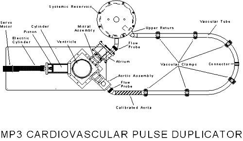
Figure 1: Pulse duplicator showing the calibrated portion of the vascular tube located at the aortic valve/aorta transition.
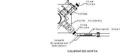
Figure 2: Calibrated aorta close-up shown with bifurcated device inside. Length displacement indicators are LVDTs.
The pulse duplicator system with an empty synthetic aorta was tested at an output of 8.75 Lpm, a pulse rate of 90 bpm, and a pulsatile inlet pressure of 120/80mm Hg. The longitudinal displacement of the aorta between the aortic valve and eventual location of the most proximal portion of the deployed stent-graft was measured at the height of each pulse. The low level of pressure dropped across this length of the aorta resulted in a small lengthening (1-2mm).
The bifurcated prosthetic device was then deployed into the synthetic aorta, and the pulsatile experiment repeated. During this experiment 100 cycles were measured and the change in length of the aorta was determined for each cycle.
In order to use the loading information generated during the pulse duplicator portion of the experiment in an accelerated frequency type test, it was important to evaluate the frequency response of an isolated barb/stent segment section (Figure 3). An isolated barb section was cut out from a supplied full prosthetic device. This small barb section with the spring joint was mounted onto a cyclic micromechanical tester (model LB50) to determine its properties at different frequencies. This barb was loaded at 16 grams per cycle, and testing began at 90 bpm. At this frequency the simple modulus (not using the diameter of the wire as a correcting factor), was approximately 600 grams per millimeter.
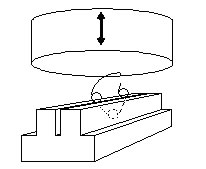
Figure 3: Close-up of micromechanical compression tester used to evaluate bending modulus vs. frequency
The frequency of the test was gradually increased up to 50 Hz to determine the modulus vs. frequency characteristics of this barb/stent segment.
The final portion of the testing involved loading a segment of the prosthetic stent-graft including barbs, connection sutures and vascular graft material. This segment was isolated and mounted onto a special adapter plate in the lower grip of a micromechanical tester (Figure 4). In the upper grip was a piece of the same type of aortic material used in the primary flow testing previously mentioned. The edge of this aorta material was cut to equal the angle of the barb pair that it would be resting on in vivo . Initially a series of modulus vs. frequency tests were run and the preliminary results indicated that the device could only be tested up to approximately 8 Hz. This is probably because of the influence of the sutures, graft material and latex on the response time of the whole segment. The remainder of this experiment was to repeatedly load the pair of barbs at a total loading of 40 grams (2 x 20 grams for each barb) at a frequency of 8 Hz. Throughout the testing, the stress strain curves of this experiment were measured on a weekly basis. This experiment was continued until the segment was exposed to 400 million cycles.
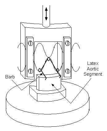
Figure 4: Accelerated durability set-up including segment of stent-graft/barb/suture combination.
Results
The result of the first experiment was that the aorta, proximal to the location of the piercing barbs, was extended approximately 7.0mm. This indicated that the total load on the barb line of the aorta was 120 grams. Assuming that each barb of the three two-barb pairs was experiencing equal loading, we determined that each barb in this device experienced a cyclic peak loading of 20 grams.
After the barb/stent segment was mounted on the high speed micromechanical tester, it was determined that the modulus of the barb wire itself remained constant until a frequency of 50 Hz was attained. This indicated that the barb itself could have been tested in a durability tester up to a frequency of 50 Hz. The frequency response testing of the barb/stent-graft/suture segment, however, showed that the modulus of this segment (which varied with each individual sample used) was maintained only up to a testing frequency of approximately 8 Hz.
Table 1 is a summary of the data obtained during each month of durability testing of the barb/stent-graft/suture segment. This represents the stress strain curve or a simple modulus of that particular cycle and also represents the steepest portion of the rising part of the curve. Ten cycles were measured in each case and the modulus of these ten cycles was approximately the same.
Table 1
|
Cycles x 10E6
|
Modulus
|
|
0
|
243
|
|
25
|
297
|
|
100
|
520
|
|
133
|
192
|
|
184
|
454
|
|
223
|
194
|
|
260
|
118
|
|
298
|
224
|
|
319
|
537
|
|
360
|
609
|
|
382
|
571
|
|
400
|
513
|
Although the modulus of all cycles within each day the testing was carried out were the same, the modulus of the sample from time period to time period is somewhat erratic. It was assumed that the modulus of the composite test sample was lower than that of the wire itself due to other contributing factors, such as the tightness of the sutures holding the metal, the exact angle of the barb coming out of the graft, and even the tightness of the graft material to which this whole set up is attached. It is possible that changes in these less controlled factors might account for this variable data. It was considered that perhaps wear in the synthetic aortic, due to the barb cutting into the latex could represent the change in modulus. However, the wear hole in the latex (0.02mm) does not represent a large enough number to explain the variation in the results.
Another possibility, particularly at the end of the testing where the modulus seems to be climbing, is that the looseness of the fabric has been reduced. This would be difficult to evaluate in this test.
Discussion
At the end of 400 million cycles, there was no indication of weakening or breaking of the barbs during testing. There was also no change in the angle that the barb made with the body of the stent-graft itself. And finally, there was no obvious change in the fabric in the region around the barb mounting area. These results indicate that, under the testing conditions that these samples have been exposed to, there is no breakage or obvious change in the tested barbs. There is, at the end of the testing, an indication of an increasing modulus. If this were to continue, and was indeed a change in the individual barb itself rather than the fabric, then at cycles greater than 400 million there might be increasing brittleness of the metal.
This approach to evaluating the drag induced load on the barbs, the frequency response of the barb and the barb full device package, and the durability testing appears to have resulted in the best control to date of this rather complex durability problem.
Conclusion
Isolated segment barb testing can successfully evaluate the durability of barbs on stent-grafts.
References
1) Folkow, B., Neil, E., Circulation , New York : Oxford University Press, 1977.
2) Conti, J.C., Greisler, H., NHLBI Contractor’s Meeting, Louisville, KY, 1989.

